


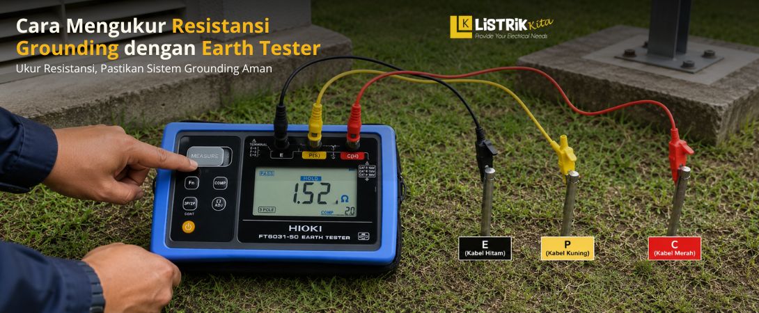
Grounding is an important part of an electrical installation. It provides a path for unwanted electrical current to flow safely into the ground. A properly installed grounding system can help reduce the risk of electric shock and protect electrical equipment from certain electrical faults.
However, having a grounding electrode does not automatically mean that the grounding system is working properly. Its condition should also be checked regularly by measuring its resistance. One common method is to use an earth tester.
What Is Grounding Resistance?
Grounding resistance is the amount of resistance between a grounding system and the earth. This measurement is commonly given in Ohms (Ω).
A lower resistance generally means there is less resistance to the flow of current into the ground. On the other hand, a high resistance value may indicate that the grounding system needs further inspection.
Measuring grounding resistance helps determine the condition of the grounding electrode and provides useful information about the performance of the grounding system.
Preparation Before Measuring Grounding Resistance
Before starting the measurement, prepare the required equipment and check the area around the main grounding electrode. Proper preparation can help make the measurement process easier and more consistent.
Use an Earth Tester
An earth tester is a measuring instrument designed to check grounding or earth resistance. Make sure the tester is in good condition and has the appropriate measuring cables.
Check the cables, terminals, and connectors before use. Make sure there are no damaged parts or loose connections that could affect the measurement.
Prepare Two Grounding Spikes
The three-point measurement method requires two additional grounding spikes. These spikes are placed in the ground at specific positions from the main grounding electrode.
One spike works as the potential electrode, while the other works as the current electrode. The distance between the electrodes should follow the measurement method and the instructions provided with the earth tester.
Make Sure the Grounding Area Is Clean
Check the area around the main grounding electrode before starting the measurement. Remove dirt, grass, or other objects that could interfere with cable connections or access to the electrode.
The work area should also be safe and easy to access so the measurement can be performed properly.
Steps to Measure Grounding Resistance with an Earth Tester
Once the equipment and measurement area are ready, the measurement can be performed step by step.
Turn Off the Power Source If Required
Safety should always come first. If required by the installation procedure or working conditions, turn off the power supply and make sure the area being checked is not energized.
Electrical measurements should be performed by someone who understands basic electrical safety procedures.
Connect the Earth Tester to the Grounding Electrode
Connect the earth tester to the main grounding electrode using the measuring cable. Make sure the cable is connected securely to the correct terminal.
A loose or incorrect connection can affect the measurement result.
Install the Two Spikes in the Ground
Place the two spikes in the ground along the measurement path from the main grounding electrode. One spike is used as the potential electrode, while the other is used as the current electrode.
The distance between the main electrode and the spikes should follow the recommended measurement method and the instructions from the earth tester manufacturer.
Connect the Cables to Each Spike
Connect the earth tester cables to both spikes according to the correct terminals. Check all connections again before starting the measurement.
Make sure the spikes are firmly installed and the cables will not come loose during the test.
Perform the Measurement
Turn on the earth tester and start the measurement according to the instrument's instructions. Once the measurement is complete, the grounding resistance value will appear on the display.
Do not rely on only one reading if the result needs to be verified. Repeat the measurement when necessary to check whether the readings are reasonably consistent.
Record the Measurement Result
Record the resistance value shown on the earth tester in Ohms (Ω). The result can then be compared with the applicable requirements or standards for the electrical installation being tested.
Keeping measurement records can also make future grounding inspections easier.
How to Read Grounding Resistance Results
Understanding the Value in Ohms
The value shown by the earth tester represents the resistance of the grounding system to earth. In general, a lower value means there is less resistance to current flowing into the ground.
However, there is no single resistance value that applies to every type of electrical installation. The acceptable value depends on the system design, installation type, applicable standards, and technical requirements.
What to Do If the Resistance Is Too High
If the measurement shows a high resistance value, check the grounding electrode, cable connections, and soil conditions around the grounding area.
Depending on the results of the inspection, the grounding system may require connection repairs, electrode improvements, or other technical adjustments. These tasks should be handled by someone with suitable electrical knowledge and experience.
Tips for More Accurate Grounding Measurements
Make Sure the Spikes Are Properly Installed
The spikes should be firmly inserted into the ground to maintain a stable connection during the measurement.
Check the Earth Tester Cables and Terminals
Damaged cables or loose terminals can affect the reading. Always inspect the measuring equipment before use.
Take Several Measurements
Repeating the measurement can help confirm that the results are consistent. If the readings vary significantly, check the spike positions and cable connections again.
Follow the Instrument's Instructions
Different earth testers may have different operating procedures. Always follow the manufacturer's manual and recommended measurement method.
Common Mistakes When Measuring Grounding
Several mistakes can affect the accuracy of a grounding resistance measurement. These include incorrect spike spacing, loose cable connections, or spikes that are not firmly installed in the ground.
Another common mistake is failing to inspect the tester before use or relying on a single measurement without checking the result again.
By following the correct procedure and paying attention to both the equipment and the measurement area, grounding resistance testing can provide more reliable information about the condition of an electrical grounding system.
